Overview of LVDS interface
Overview
LVDS=Low-Voltage Differential Signaling,The core of this technology is the use of very low voltage swing high speed differential transmission data, has the following characteristics:
- Low power consumption
- Low bit error rate
- Low crosstalk
- Low jitter
- Low radiation
- Good signal integrity
- The maximum data transfer rate is 655Mbps, which can theoretically reach 1.923Gbps
- It is widely used in LCD monitors of 17inch and above
Hardware Structure
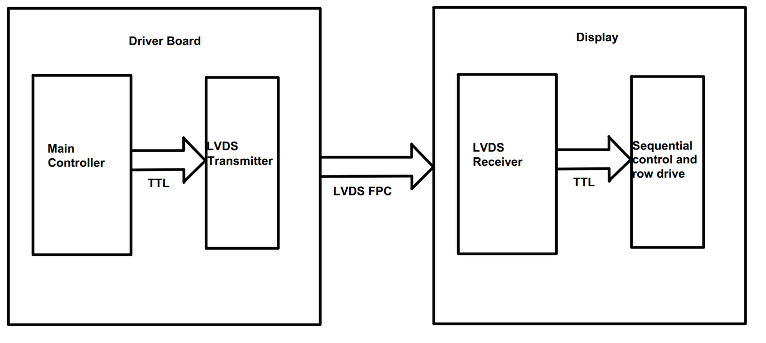
LVDS signal transmission consists of three parts : differential signal transmitter, differential signal interconnector, differential signal receiver.
- Differential signal transmitter : The TTL signal of unbalanced transmission is converted into LVDS signal of balanced transmission. There are independent and integrated.
- Differential signal interconnector : Including connecting wire (cable or PCB routing), terminal matching resistance. According to IEEE regulations, the resistance is 100 Ohm. We usually choose 100, 120 Ohm.
- Differential signal receiver : Convert LVDS signals from balanced transmission to TTL signals with high input impedance.

Type of Interface
- Single channel 6-bit LVDS:Adopt single channel transmission, each primary color uses 6 bits of data, a total of 18 bits of RGB data.
- Dual-channel 6-bit LVDS: Dual-channel transmission is adopted, with 6 bits of data for each primary color, 18 bits of odd path data and 18 bits of even path data, a total of 36 bits of RGB data.
- Single channel 6-bit LVDS:Adopt single channel transmission, each primary color uses 8 bits of data, a total of 24 bits of RGB data.
- Dual-channel 6-bit LVDS: Dual-channel transmission is adopted, with 8 bits of data for each primary color, 24 bits of odd path data and 24 bits of even path data, a total of 48 bits of RGB data.
Transmitting chip
The LVDS sending chip converts the TTL level RGB data signals input in parallel into serial LVDS signals, which are directly sent to the LVDS receiving chip on the LCD panel.
- Four channel LVDS send chip:Contains three data signal channels (including RGB, data enable, line synchronization, field synchronization signals) and a clock transmission channel; It is mainly used to drive the 6bit LCD panel, which can form a single or odd-even dual 6bit LVDS interface circuit.
- Five channel LVDS send chip:Contains four data signal channels (including RGB, data enable, line synchronization, field synchronization signals) and a clock transmission channel; It is mainly used to drive the 8bit LCD panel, which can form a single or odd-even dual 8bit LVDS interface circuit.
- Ten channel LVDS send chip:Contains eight data signal channels (including RGB, data enable, line synchronization, field synchronization signals) and two clock transmission channel; It is mainly used to drive the 8bit LCD panel, which can form a odd-even dual 8bit LVDS interface circuit.
Input Signal
Input data signal:
For example, a 6 bit LCD panel uses a four-channel LVDS sending chip with a total of: 18 RGB signals +1 data enable signal +1 row synchronization signal +1 column synchronization signal = 21 data input pins
Input clock signal:
This is the pixel clock signal, also known as the data shift clock (the shift register is used to convert the input parallel RGB data into serial data in the LVDS sending chip). The pixel clock signal is the basis for transmitting data and reading data signals.
Standby control signal:
When this signal is valid (usually at low level), the power supply to the clock PLL PLL circuit in the LVDS sending chip will be turned off and the IC output will be stopped.
Data sampling selection signal:
Used to select whether to use the rising or falling edge of the clock to read RGB signal data.
Output Signal
Clock output:
The frequency of the output signal is the same as that of the input signal, occupying a channel of the sending chip.
Serial data signal output:
Four - channel transmission chip, serial data occupy three channels
The output data format of the LVDS sending chip on the LCD driver board must be the same as that required by the LVDS receiving chip on the LCD panel; otherwise, the driver board does not match the LCD panel.

Aquilino
Very important information.
Request I am trying to connect a panel 46_ksz_s100_srl v0 to samsung mainboard BN94-05011H 46 inches.
I appreciate your help.
Aquilino
Very important information.
Request I am trying to connect a panel 46_ksz_s100_srl v0 to samsung mainboard BN94-05011H 46 inches.
I appreciate your help.
Wolfgang w.Scharpenberg
can you please offer 300 / 1000 pcs converter rgb ttl to LVDS